High-speed digital signals do not stay perfectly clean as they travel through PCB traces, backplanes, connectors, and cables. Loss increases with frequency, edges become less distinct, and timing uncertainty can grow until a receiver struggles to distinguish one bit from the next.
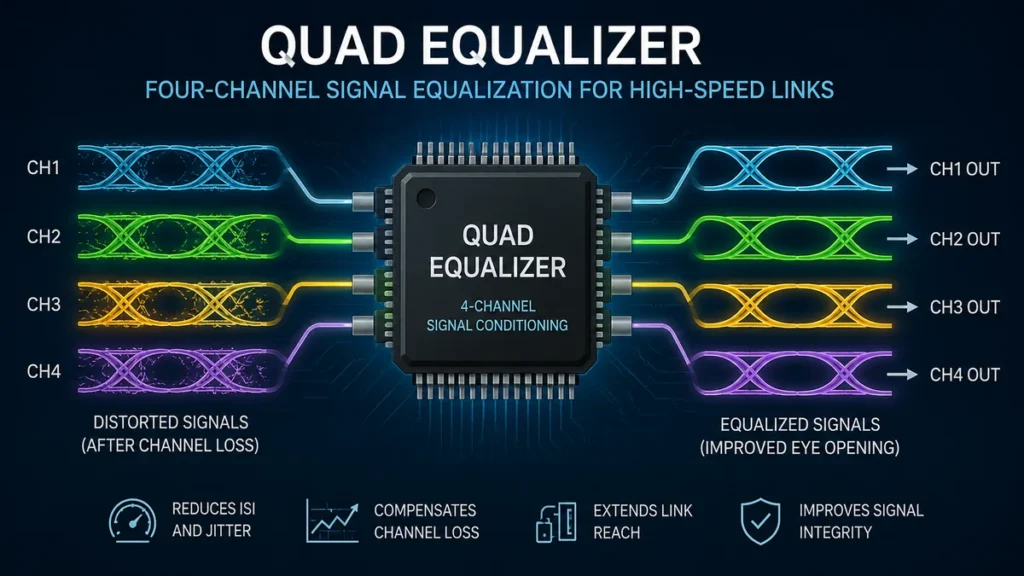
A quad equalizer addresses this problem across four signal channels at once. Instead of processing audio frequencies, the term commonly refers in high-speed electronics to an integrated signal-conditioning device that compensates for transmission losses on four serial data paths. Devices in this category are used with technologies such as DisplayPort, PCI Express, backplanes, and high-speed cables.
Quick answer: A quad equalizer is a four-channel signal-conditioning circuit that compensates for frequency-dependent losses introduced by cables or PCB traces. By boosting attenuated high-frequency components and reshaping received signals, it can improve eye opening, reduce deterministic jitter, and help four high-speed serial links operate reliably over longer or more challenging interconnects.
What Is a Quad Equalizer?
A quad equalizer contains four equalization channels in a single device. Each channel receives a degraded high-speed signal and applies compensation intended to counter losses introduced by the transmission medium.
This is particularly useful because modern digital interfaces frequently use multiple lanes.
A typical channel may contain:
- Input termination
- Receive equalization
- A limiting or gain stage
- DC-offset correction
- Signal detection
- Output driver circuitry
- Channel enable or standby control
For example, Texas Instruments’ DS32EV400 implements four data channels, with each channel containing an equalizer stage, limiting amplifier, DC-offset correction circuitry, and a CML driver.
The objective is not to recreate missing digital information. Instead, equalization compensates for predictable analog distortion before it becomes severe enough to cause bit errors.
Why High-Speed Signals Need Equalization
A digital waveform may appear to consist simply of ones and zeros, but physically it is an analog electrical signal traveling through a transmission medium.
That medium is imperfect.
Copper traces, connectors, vias, and cables introduce attenuation. More importantly, the amount of attenuation is frequency-dependent. High-frequency components responsible for sharp transitions are often attenuated more heavily than lower-frequency components.
As the data rate rises, this becomes increasingly significant.
Insertion Loss
A PCB trace or cable reduces signal amplitude as distance increases. The effect can become severe over long FR4 traces or cables.
Without compensation, the signal arriving at the receiver may have significantly less high-frequency energy than the transmitted waveform.
Inter-Symbol Interference
One bit can effectively influence the bits that follow it when the channel does not preserve sufficiently fast transitions.
This phenomenon is known as inter-symbol interference (ISI).
Instead of seeing a clean transition between logical states, the receiver sees overlapping responses from neighboring symbols. Texas Instruments describes equalization in devices such as the DS50EV401 as a way to reopen an input eye affected by ISI from the channel interconnect.
Deterministic Jitter
Channel losses can also shift the apparent timing of transitions in a predictable, data-dependent manner.
This contributes to deterministic jitter.
When jitter becomes excessive, the receiver has a smaller timing window in which it can correctly sample each bit.
A Closed Eye Diagram
Engineers often evaluate these effects with an eye diagram.
A healthy eye has a relatively wide horizontal and vertical opening. A badly degraded signal produces a smaller opening—or, in extreme cases, what engineers describe as a closed eye.
Equalization attempts to restore enough signal quality to make reliable receiver decisions possible.
How a Quad Equalizer Works
The core idea behind a quad equalizer is straightforward: compensate for the characteristics of the channel rather than simply amplifying everything equally.
Ordinary broadband amplification would increase both wanted and unwanted components. Equalization instead provides frequency-dependent compensation.
1. The Signal Enters the Receiver
Each differential data channel enters its corresponding receiver input.
Many high-speed equalizers use differential signaling because it offers good noise immunity and works well at multi-gigabit data rates.
Some devices employ current-mode logic (CML) inputs and outputs. The DS32EV400, for example, uses differential CML interfaces.
2. Equalization Compensates for Channel Loss
The receive equalizer applies more compensation where the transmission path has introduced greater attenuation.
Conceptually, if the cable or PCB behaves like a low-pass network that weakens higher-frequency components, the equalizer provides a response designed to counter that loss.
The resulting waveform should have sharper transitions and a more usable eye opening.
3. Additional Signal Conditioning Takes Place
Depending on the IC, the equalized signal may then pass through circuitry such as:
- Limiting amplifiers
- Offset-correction blocks
- Output drivers
- Polarity-control circuits
- Signal-detection logic
- Output emphasis stages
Not every quad equalizer implements the same architecture.
Some are receive-only equalizers, while others combine equalization with redriver, preemphasis, or deemphasis functions.
4. The Conditioned Signal Is Driven Forward
The restored signal leaves the device and travels toward the final receiver or another section of the interconnect.
This is why equalizers and redrivers are often strategically positioned along difficult signal paths.
Quad Equalizer vs. Redriver
The terms equalizer and redriver are related, but they are not always interchangeable.
| Function | Equalizer | Redriver |
|---|---|---|
| Compensates for channel loss | Yes | Usually |
| Receive equalization | Core function | Common |
| Restores output amplitude | Depends on design | Yes |
| Output emphasis | Not always | Often |
| Retimes data with a recovered clock | No | No |
| Four-channel implementation possible | Yes | Yes |
A basic receive equalizer concentrates on compensating for loss before receiver decisions are made.
A redriver generally combines receive-side equalization with active output-drive circuitry so that the conditioned signal can travel through another section of the channel.
Analog Devices’ MAX14950 illustrates this approach. It combines programmable input equalization with programmable redrive circuitry and output emphasis for PCI Express links.
This distinction also explains why a redriver should not automatically be called a retimer.
A retimer typically performs clock and data recovery before transmitting a newly timed signal. A conventional analog redriver conditions the existing waveform without performing complete clock recovery.
Why Four Channels Matter
The word quad simply means that the IC contains four channels.
Putting four equalizers in one package provides several practical advantages.
Compact Board Layout
One four-channel IC can occupy less PCB area than four independent devices.
That matters in servers, storage hardware, industrial computers, communications systems, graphics equipment, and other space-constrained designs.
Consistent Channel Architecture
Multiple lanes of the same interface can be conditioned with the same device family and similar electrical characteristics.
Lower Component Count
Combining four channels can reduce:
- Package count
- Power-routing complexity
- Control circuitry
- PCB routing overhead
- Bill-of-materials complexity
The tradeoff is that placement becomes important. All four channels must be routed sensibly to the same IC without creating unnecessary stubs, skew, crosstalk, or trace length.
Programmable Equalization
Not every transmission channel has the same loss.
A short PCB trace may need very little compensation. A long cable or backplane may require substantially more.
That is why many quad equalizers offer programmable equalization levels.
The DS32EV400 provides eight levels of input equalization and supports configuration through control pins or SMBus. Texas Instruments specifies compensation of up to 14 dB of loss at 3.2 Gbps for this device.
Programmability allows an engineer to tune compensation according to the actual channel.
Too little equalization may leave the signal under-compensated.
Too much can over-emphasize high-frequency content, increase noise sensitivity, and distort the waveform in a different way.
The best setting is therefore not automatically the maximum available boost.
Quad Equalizer Applications
The exact application depends heavily on the device’s bandwidth, protocol features, electrical interface, and channel architecture.
DisplayPort
DisplayPort uses multiple high-speed lanes, making a four-channel architecture a natural fit for certain implementations.
The DS32EV400 is specifically identified by Texas Instruments as a DisplayPort quad equalizer. It supports four channels and operation up to 3.2 Gbps, while also being applicable to other high-speed transmission systems.
Equalization can become valuable when PCB and cable losses make the available DisplayPort channel margin too small.
PCI Express
PCI Express is another major application for multi-gigabit equalizers and redrivers.
Analog Devices’ MAX14950 and MAX14954 are examples of quad equalizer/redriver devices intended to improve PCIe signal integrity. The MAX14950 supports PCIe Gen III at 8.0 GT/s, Gen II at 5.0 GT/s, and Gen I compatibility at 2.5 GT/s.
In a PCIe system, an equalizer/redriver can help compensate for loss introduced by long motherboard traces, connectors, risers, or cables.
Backplanes
Backplanes may contain relatively long copper routes, connectors, and vias.
At multi-gigabit rates, those structures can create substantial insertion loss and ISI. Equalization helps recover margin that would otherwise be lost.
High-Speed Cables
Cable attenuation generally increases with frequency and length.
A quad equalizer can therefore be useful when several serial lanes need to cross a cable whose insertion loss would otherwise exceed the receiver’s capabilities.
Storage and Communications Equipment
Depending on the particular component, related devices may support or work with interfaces such as:
- SAS
- SATA
- XAUI
- InfiniBand
- Fibre Channel
- Interlaken
For example, the MAX3987 was designed as a four-channel receive/transmit equalizer supporting applications including PCIe-compatible links, XAUI, Fibre Channel, Interlaken, InfiniBand, SAS-2, and SATA Revision 3 OOB signaling.
Protocol compatibility should always be verified from the specific device datasheet rather than inferred simply because a component has sufficient nominal bandwidth.
Equalization, Preemphasis, and Deemphasis
These terms describe related approaches to overcoming channel loss.
Receive equalization operates after the signal has traveled through the lossy medium. The receiver boosts or otherwise compensates for frequency components that have suffered greater attenuation.
Preemphasis modifies the transmitted waveform so selected high-frequency components or transitions receive greater amplitude before entering the channel.
Deemphasis changes the relative amplitude of portions of the transmitted waveform to achieve a similar goal: improving the received signal after frequency-dependent channel loss.
Some quad devices combine receive equalization with output preemphasis.
The MAX3987, for example, combines four-channel receive equalization with programmable transmit preemphasis.
The techniques can therefore complement each other rather than being competing concepts.
Important Specifications in a Quad Equalizer
Selecting or understanding a quad equalizer requires more than looking at its maximum data rate.
Supported Data Rate
The equalizer must support the intended signaling rate with sufficient margin.
Examples vary considerably. The DS32EV400 is optimized up to 3.2 Gbps, while other equalizer families target substantially higher data rates.
Equalization Range
Equalization capability is commonly expressed in decibels at a particular frequency or data rate.
A larger number does not automatically make one device superior. What matters is whether the equalizer’s response matches the loss characteristics of the actual channel.
Jitter Performance
An equalizer should repair channel-induced distortion without introducing excessive additional jitter.
Useful datasheet parameters may include:
- Random jitter
- Deterministic jitter
- Residual jitter
- Unit interval measurements
- Propagation delay
Input and Output Interface
Designers should verify electrical compatibility, including:
- Differential voltage levels
- Input common-mode range
- Termination
- CML or other signaling architecture
- AC/DC coupling requirements
The DS32EV400 supports both AC- and DC-coupled data paths and a wide input common-mode range.
Power Consumption
Four high-speed analog channels can consume meaningful power.
Power matters not only for system efficiency but also for thermal design, especially when several signal-conditioning ICs are used on one board.
Channel Controls
Some devices provide independent controls for each channel.
These may include:
- Enable
- Standby
- Signal detect
- Equalization level
- Output amplitude
- Preemphasis
- Polarity inversion
Independent controls can reduce unnecessary power consumption and make troubleshooting easier.
AC Coupling vs. DC Coupling
Another design consideration is whether the high-speed link is AC-coupled or DC-coupled.
AC coupling places capacitors in the signal path. These block DC while allowing changing components of the signal to pass.
DC coupling preserves the DC component but requires compatible common-mode conditions between connected circuits.
A quad equalizer that supports both approaches provides additional flexibility, but the surrounding system still has to satisfy the component’s input common-mode and bias requirements.
This is one reason datasheet application diagrams matter. A part may have the right data-rate specification yet still be unsuitable if its electrical interface does not match the rest of the system.
Understanding Eye Diagrams When Tuning Equalization
An eye diagram is one of the most useful tools for evaluating equalizer performance.
Repeated bit transitions are superimposed on an oscilloscope display, producing a shape resembling an eye.
Engineers typically examine:
- Vertical eye opening
- Horizontal eye opening
- Crossing behavior
- Noise
- Rise and fall characteristics
- Jitter
- Overshoot and ringing
The goal is not simply to make the waveform look sharper.
A good equalization setting should produce adequate receiver margin while avoiding excessive boost, noise amplification, or ringing.
This is where practical testing matters. A setting that looks appropriate based only on trace length may not be optimal once connectors, vias, cable characteristics, manufacturing tolerances, and actual transmitter behavior are included.
Common Quad Equalizer Design Mistakes
Equalizers can provide significant signal-integrity improvement, but they cannot rescue every poor channel.
Using Maximum Equalization by Default
More compensation is not automatically better.
Over-equalization can exaggerate high-frequency noise and create overshoot or other distortion. Start with channel-loss estimates and verify the result through measurement or simulation.
Ignoring PCB Layout
A powerful equalizer cannot compensate for every layout problem.
Poor routing can introduce:
- Impedance discontinuities
- Reflections
- Crosstalk
- Stubs
- Excessive via loss
- Return-path discontinuities
High-speed differential routing practices still apply before and after the device.
Placing the Equalizer in the Wrong Location
Device placement depends on architecture.
Some receive equalizers are intended to sit close to the final endpoint. Other redrivers can be positioned where they divide a difficult channel into manageable sections.
For example, documentation for the DS50EV401 describes it as a unidirectional receiver intended for placement close to the link endpoint.
Follow the architecture recommended for the specific component rather than assuming every equalizer should sit halfway along a trace.
Choosing by Data Rate Alone
Two equalizers with the same headline speed can behave very differently.
Protocol requirements, electrical idle handling, receiver detection, coupling method, output characteristics, equalization range, jitter, and control interfaces may all matter.
Expecting Equalization to Fix Fundamental Channel Problems
Equalization compensates primarily for predictable channel loss.
It does not magically remove severe reflections, incorrect impedance, broken return paths, excessive crosstalk, or a fundamentally noncompliant PCB design.
Fix the physical channel first whenever possible.
Quad Equalizer vs. Retimer
One of the most useful distinctions in high-speed system design is between an equalizer/redriver and a retimer.
A quad equalizer or redriver works mainly in the analog signal domain. It compensates for channel loss and drives a cleaner version of the incoming waveform forward.
A retimer performs clock and data recovery and generates newly timed output data.
This difference affects:
- Latency
- Cost
- Power consumption
- Protocol complexity
- Maximum channel extension
- Jitter-cleaning capability
An equalizer/redriver often provides a simpler, lower-latency solution when the original timing information remains sufficiently recoverable.
A retimer becomes more useful when accumulated jitter and channel degradation require actual clock recovery rather than analog conditioning alone.
How to Choose a Quad Equalizer
A practical selection process starts with the channel rather than the component catalog.
- Identify the protocol and lane rate. Determine the actual signaling rate and protocol-specific requirements.
- Estimate total channel loss. Include PCB traces, vias, connectors, cables, and other discontinuities.
- Check the equalization range. Confirm the device can compensate for the expected loss at the relevant frequencies.
- Review jitter specifications. Make sure the signal conditioner preserves sufficient timing margin.
- Verify electrical compatibility. Check termination, common-mode voltage, coupling method, supply voltage, and differential interface requirements.
- Check protocol-specific features. PCIe designs, for example, may require behavior such as electrical idle and receiver detection.
- Consider placement and layout. Keep high-speed routes controlled and follow the manufacturer’s recommended PCB practices.
- Measure the completed link. Validate performance with appropriate signal-integrity testing instead of assuming the theoretical design is sufficient.
The last step is particularly important. Real hardware includes losses and discontinuities that simplified calculations may underestimate.
Real-World Quad Equalizer Examples
Several devices illustrate how broad the category can be.
Texas Instruments DS32EV400
The DS32EV400 is a programmable four-channel equalizer associated particularly with DisplayPort and other high-speed serial applications.
Key characteristics include four channels, operation up to 3.2 Gbps, eight programmable equalization levels, SMBus or pin configuration, and compensation for up to 14 dB of loss at 3.2 Gbps.
Analog Devices MAX14950
The MAX14950 is a quad PCI Express equalizer/redriver.
It supports PCIe Gen III, Gen II, and Gen I data rates and combines programmable receive equalization with programmable output emphasis. Analog Devices specifies very low typical propagation delay of 160 ps for the device.
Analog Devices MAX14954
The MAX14954 follows the same broad signal-conditioning concept for PCI Express systems. It combines programmable input equalization and redrive circuitry and is intended for stripline, microstrip, and balanced 100-ohm cable applications.
These examples also show why quad equalizer describes an architectural category rather than one universal specification.
Does a Quad Equalizer Increase Cable or Trace Reach?
It can—but there is no universal distance increase.
The achievable improvement depends on:
- Cable type
- PCB material
- Trace geometry
- Connector losses
- Data rate
- Transmitter quality
- Receiver sensitivity
- Equalizer capability
- Jitter budget
The correct engineering question is therefore not, “How many extra meters does an equalizer provide?”
It is, “Can the equalizer compensate for the measured or modeled channel loss while keeping the complete link within its signal-integrity requirements?”
That approach remains valid across cables, backplanes, and motherboard traces.
Is a Quad Equalizer the Same as a Four-Band Audio EQ?
No.
This distinction matters because the word equalizer is also common in audio equipment.
An audio equalizer adjusts audible frequency bands to change tonal balance. A four-band audio EQ might separately control bass, low-mid, high-mid, and treble ranges.
A high-speed quad equalizer, by contrast, generally refers to four data channels being equalized simultaneously. The “quad” describes the number of signal paths rather than the number of adjustable frequency bands.
There are also professional audio products that use “Quad EQ” in their product names, so context remains important. In high-speed semiconductor documentation, however, the term commonly identifies a four-channel signal-conditioning architecture.
The Role of Quad Equalizers in Modern Signal Integrity
As serial interfaces become faster, the physical transmission channel consumes a larger share of the overall link budget.
PCB traces that behaved almost transparently at lower frequencies can become significant sources of attenuation at multi-gigabit speeds. Connectors, vias, and cables add further losses.
That makes signal conditioning increasingly important.
A quad equalizer provides a practical way to compensate four high-speed channels in a compact device. Depending on the implementation, it can counter frequency-dependent attenuation, reduce the effects of ISI and deterministic jitter, improve eye opening, and extend the usable reach of a high-speed interconnect.
The key is to treat equalization as part of the complete signal-integrity design rather than as a repair tool for a poor PCB. Start with controlled impedance, clean routing, appropriate connectors, and a realistic channel-loss budget. Then select and tune the quad equalizer to compensate for the loss that remains.
Used this way, equalization can turn a marginal four-lane link into a robust one without the complexity of full clock-and-data recovery.